
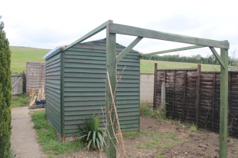
In 2014, a year after we moved into our new house, i converted an old garden shed into a roll-off-roof Observatory.
Mary wrote a fantastic blog which can be read here, but i wanted to complement that with a more technical note.
Background
Mary and I had both always had a dream of having a garden observatory. So when we bought a house in a little Oxfordshire village, a key criterion was that it should have a nice dark garden. This was so important to us that before we put in an offer, we sneaked into the garden at night and checked it out (don’t worry, the house was unoccupied !).
The house has a long garden backing onto a low but steep hill, and a little orchard half way up which provides a lovely screen blocking the village lights. The end of the garden was very dark – so we put in an offer!
The garden had one other item of considerable interest – an old dismantled garden shed. So, in March 2014, we hatched a plan to make our dream a reality.
Choosing a Type of Observatory
Its important to build an observatory that you’ll use. Domes are very nice, but often impractical for small gardens and for large scopes, and they’re also quite expensive. Rooftop observatories also look cool, but heat from the house can mess with imaging, and they’re complicated to build. A much more popular solution is a shed with a roll-off or swing-off roof. Swing-off roof designs are a bit like the lid on a Kilner jar and hinge off to one side. Roll off roof designs, well, roll off!
Siting the Observatory
Choosing the right location is vital, even if you are short of space. You will want as clear a view as possible in all directions. However you also need to consider where you have light spill from neighbours’ “security” lights or from streetlights, and buildings can be useful for blocking this. It will always be a trade off.
In our case, we were able to put the observatory at the far end of the garden. Our house and the neighbours’ mask most of the streetlights, and our garden fence shields us from the insecurity lights two doors up.
You also need to think about which way the roof is going to roll off. You will have restricted visibility in the direction that it rolls because the roof end will stick up a bit. We rolled ours off to the South, where the sky was partly obscured by our house anyway. We also made the runners extra-long so we could roll it well past the end of the shed.
Design Decisions
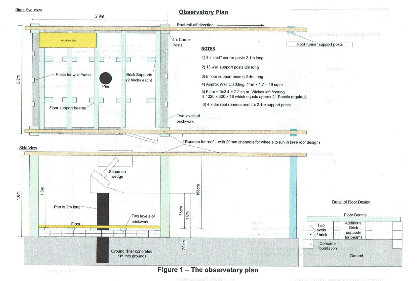
There are many roll-off roof designs on the internet. We followed the one shown here – sadly the website we got it from has since died but we kept the plans.
The left hand image shows a plan view and side elevation of the shed itself. Key elements here are the solid foundation for the pier, and the low brick walls that the shed and its floor sit on to keep the floor away from the damp. The brick walls are set on shallow concrete strip foundations with a damp-proof membrane built-in. The pier passes through a hole in the floor but doesn’t touch it which keeps vibrations down. Further details are given in subsequent sections.
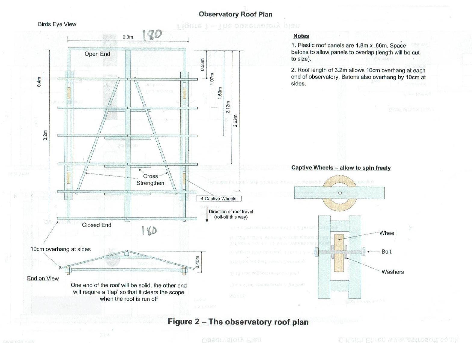
The right hand image shows the new roof design. The original roof was far too heavy, so we rebuilt it using lightweight timber and clear plastic roofing material. At each side of the roof there’s a two-part rail with wheels sandwiched between it. These fit into grooves that we cut in the long runners that we attached to the top of the walls and which extend for a further shed-length-and-a-bit beyond the end of the shed. At the far end they’re supported on stout wooden posts set in concrete.
Click on the images to see a larger version.
The Final Design
The diagrams above show the size of the original author’s shed. Ours was smaller – 2.4 metres by 1.8 metres. This was just large enough though if i could have made it a metre longer, it would have been better. In the design above, the Pier was put in the exact centre of the shed but I realised this would leave very little space at either end so i moved it 30cm closer to the southern end of the shed, with the door at the northern end. This leaves enough room for a computer desk and storage cupboard at the northern end. Our final design is shown below with South being towards the bottom.
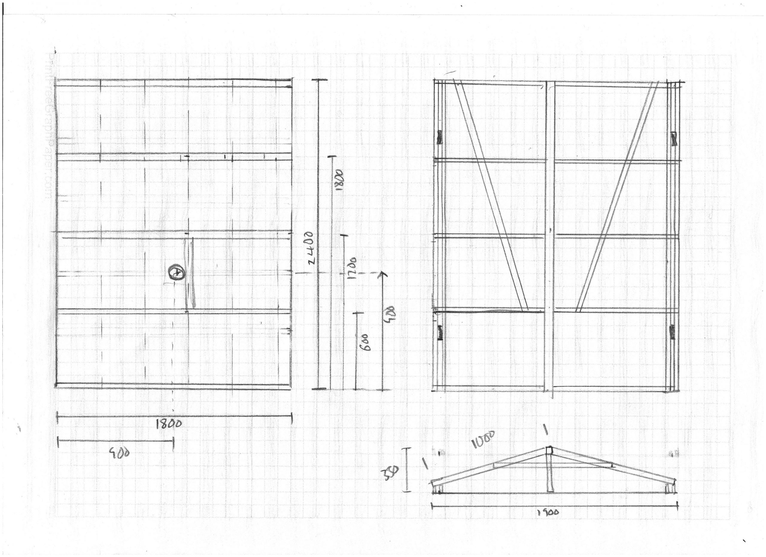
The sides of our shed were about 170 cm high. Any lower and i think it would be difficult to get into the shed, but any higher and the pier will need to be very tall in order for the telescopes to see over the walls. This would be a problem for visual observers and could make maintenance difficult. Some designs include fold-down side panels but this felt too complicated!
Building Work
List of Parts
Having completed a design, i created a list of the parts we were going to need – timber, concrete, posts, screws, nails, sheeting, paint and so on. You can find a copy here. The cost in 2014 was about £500 for all the parts excluding the shed itself.
Site Preparation
The site was cleared and levelled. Our site sloped from north to south, so i had to dig the foundations and walls into the ground at the north. However, try to keep the final floor level at least 100mm above the ground level to avoid water ingress. Also, be sure to leave some drainage holes through the walls – we forgot, and the underfloor area filled with water during a storm, which caused the boards to rot!
Corner Posts
Our shed was a flat-pack design which had originally been nailed together at the corners. This flimsy design would not have been strong enough for the repeated opening and closing of the roof so instead, i set four 75mm square posts in concrete, one at each corner, spaced so that the shed walls could be fixed between them. Its important that the posts are correctly spaced, properly set in a rectangle and are held vertical while the concrete sets.
Pier
For the pier base, I dug a large hole about 60 centimetres deep and 80cm in diameter. I hammered a 150cm length of 50mm angle-iron vertically into the ground so that about a metre was sticking out, and then poured concrete round it to fill the hole to ground level. I wanted the pier to be REALLY solid.
Once the concrete had set, i slid a 150cm length of 100mm plastic drain pipe over the iron bar. I half-filled this with concrete, well tamped down, and set it exactly vertical. I’ll finish filling it later once the walls and roof are on.
Foundation and Walls
I dug shallow foundations for the walls and poured in concrete. Once it had set I built low walls, 3 bricks high, between the four posts. I also built small brick piers at two points along each floor joist’s path. You can see these in the original plan at the top of the page.
I ran a damp-proof membrane along the top of each wall and each pier, and then laid timbers for the floor. In the original build, i only laid timbers crossways as shown in the left hand picture above. However, this proved inadequate and the floor was too “bouncy”, so i fixed short timbers between the main joists.
Floor
The floor was made from chipboard loft panels. These come in various sizes but ours were 900x300mm and the supports were spaced so that the long and short edges were always on top of a bearer. This is important for stiffness and strength.
Wooden Walls
First i cut both gable ends off at eaves height. To keep the roof stable, it needs to have its own gable ends which would collide with the shed if the ends weren’t cut square. If your shed door projects above the line of the eaves, you’ll need to shorten it and make a new top for the frame.
I then fixed the four shed walls on top of the floor and between the posts, with the door-wall at the north.
Posts for Runners
Three metres to the south of the shed, and PRECISELY in line with the long sides, i concreted two 75mm square posts into the ground. These are the end supports for the runners. I cross-braced between the two posts to make sure the whole assembly was stable.
Runners
The runners are attached to the top of the long sides of the shed, and project right out to the tops of these two posts.
To make the runners I used a router to cut a 10mm wide, 10mm deep groove along the top of four 3m lengths of 50×50 timber. The wheels in the roof were about 8mm wide and fitted nicely into these grooves. I attached one runner to the top of the shed on each side, and then extended them out to the posts using the spare lengths. To stop the roof rolling right off at the ends, i screwed a small block of wood into each groove at the very ends. Finally, i drilled drainage holes through the bottoms of the grooves every couple of feet to prevent them filling with rainwater.
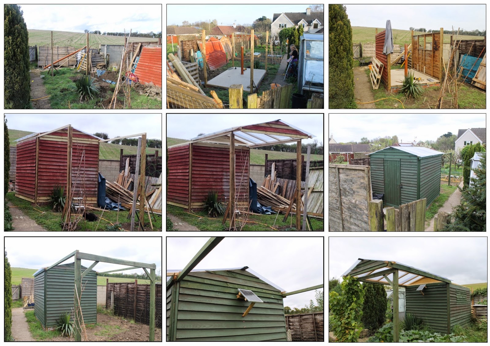
New Roof
The new roof was made from 34x44mm planed-all-round timber. I kept the same slope as the original roof. The long sides with the wheels in were made first, then the two ends were attached. Then i put in the ridge and attached the rafters along each side. I designed the roof to hang 100mm over the walls so that rainwater didn’t get inside too easily. If your shed is 180cm wide, then a 120cm sheet of roofing material will just be long enough.
The roof was clad with semitransparent corrugated plastic sheet with a pitch of 25mm and a depth of 15mm. It came in 240 x 60 cm sheets which i cut in half. Originally, i just nailed this on, but after a tornado ripped it off (!) i laid long battens on top of the replacement sheeting and screwed them down through to the rafters.
The ridge was originally sealed with stick-on fake lead. This became brittle over time and i’ve now replaced it with a long strip of damp-proof membrane which was put underneath the topmost batten on each side.
Finally, i used some spare boards to create gable-ends for the roof. These must pass over the top of the shed gable wall, but not leave too large a gap as rain will get in. Ideally you would also attach a flexible rubber flap along the bottom edge of the gable to cover any gap.
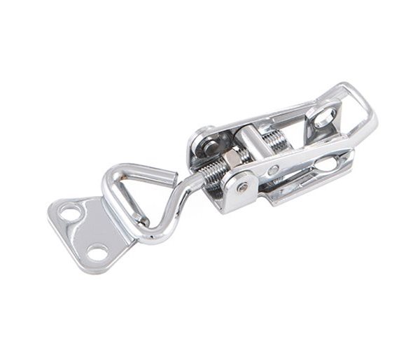
To hold the roof down in the wind – and to prevent thieves simply lifting it off! – we fitted four over-centre roof catches, like the one in the small picture at the right. These can be locked with a padlock which adds extra security if needed.
The roof was then lifted into position – a two-person job – and amazingly, it fitted, and rolled to and fro at a gentle touch!
Security
We fitted a push button combination lock to the shed door, and strengthened both the frame and door itself to make it more robust. Inside we fitted an alarm which is activated when the door is opened and deactivated by a code. There are no windows and the roof is locked down with the over-centre clips. When we’re on holiday we also padlock the clips, and remove all valuable items.
The Exterior
Once assembled, all the exterior timber was painted with green shed paint. We repaint it every few years as the British weather takes its toll.
Stopping rain coming in round the door has been difficult, and in the end we added a wide extra draft-excluder board around three sides. We also get penetrating damp blowing between the boards and onto the interior walls. We plan to remove all the exterior boarding, attach a vertical damp proof membrane and then reboard the exterior.
The Interior
The shed originally only had a single layer of boards on the outside. At first, we lined the inside of the walls with 4mm hardboard. This proved to be a mistake: the hardboard absorbed moisture, distorted and curled, even when sealed. Furthermore, its too thin to attach anything to, such as power cables or equipment. It is now being replaced with 8mm marine plywood.
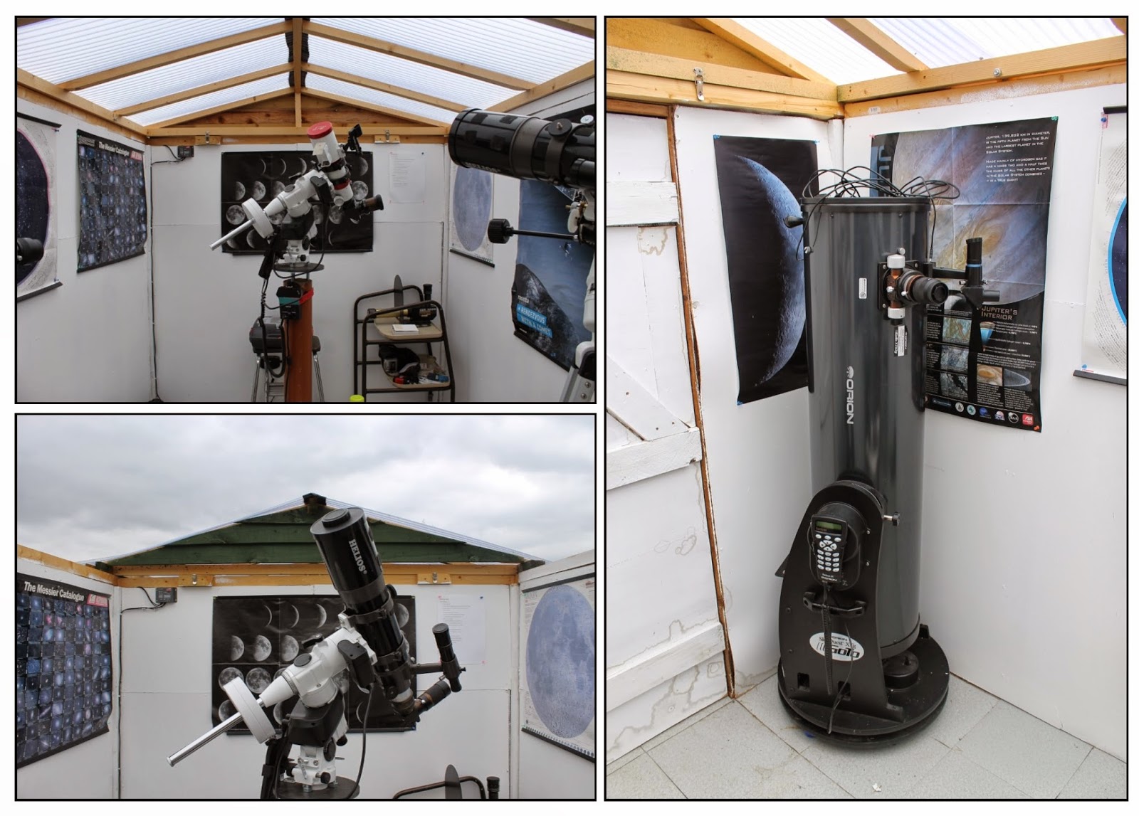
Once boarded out, the inside walls were painted with white emulsion. You might think black a better choice but you’ll be working in the dark and you need to be able to see where the walls are!
We also installed a small computer desk in the corner next to the door, with a stool under it, where the Dobsonian is in the image below. This gave us somewhere to put laptops, cameras, cables and so forth.
Finishing the Pier
The final piece of major work was the pier.
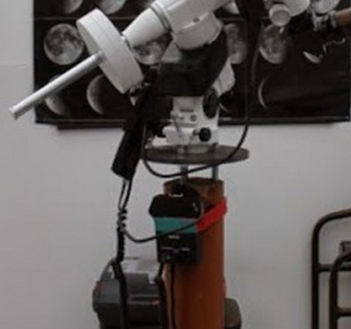
The pier needs to be high enough that your telescope can see over the walls, but not so high that you can’t shut the roof without unmounting the scope. We have a 200mm Richey Cretien on an HEQ6, and the measurements below work perfectly for it, provided we park it with the tube horizontal and facing parallel to the roof ridge.
However you should experiment with your own kit before making the final cut. If possible, put your mount on a tripod alongside the pier and see what the visibility is like at various heights.
With that in mind, i first cut the pier tube at 105cm from the floor which worked for us.
To make the pier head, I bought a 200mm diameter 10mm thick steel disk from eBay, along with three 300mm long 10mm diameter bolts with two nuts per bolt, and one additional short bolt that fits the hole in the base of our mount.
I drilled four holes through the plate. One in the very centre was to bolt the mount on. I made this hole large enough for the size of bolt that attaches the mount to a tripod.
The other three were evenly spaced about 40mm from the centre and hold the bolts that go into the pier tube but allow the disk to be adjusted perfectly horizontal. 40mm from the centre happens to be far enough out that an EQ5 mount base can fit inside them, and far enough in that an EQ6 mount base can fit around them. Your mileage may vary.
To install the bolts and plate, attach the three long bolts to the plate with one nut on either side, leaving about 5mm protruding from the top of the top nuts. The bolt heads should be hanging down.
Mark the direction of North on the outside of the tube, then fill it with wet concrete. Align one bolt with the North mark then push all three bolts down into the concrete till the plate is about 5-8 cm from the top of the tube. Slide some wooden blocks in between the plate and the tube to hold it in place, get it roughly horizontal, then leave the concrete to set.
You can see the finished article in this zoomed-in photo.
Nota Bene: you only get one shot at this. Once the concrete sets you cant remove the bolts !
Leave the concrete for at least a week before attaching a mount. To attach the mount, slip the bolt through the centre hole from below. If you find you can’t get it in, slacken the three top nuts on the plate mountings. If you find that your mount fouls on the bolt heads, you can add a spacer to lift it up from the plate.
When you attach the mount, you can use the “North” bolt to help you orientate the mount correctly. In our case, it actually fits inside the EQ6 base and we can use it as a “north post” for the mount adjusters.
Electrics and Networking
Initially, we installed solar panels onto the outside of our observatory connected via a solar regulator to two 30AH deep-cycle mobility scooter batteries. We found that two 100w panels were sufficient to charge the batteries and give us enough for a night’s imaging even in winter. We picked up the panels from our local freecycle group.
As our power needs grew, we ran mains power to the observatory. This became necessary when we installed a mini-pc to run the mount, scope and camera, and installed our meteor detection cameras on the observatory.
The mains power is also used for powerline networking, and we get about 30MB/s which is adequate for remote operation of the system.
Improvements
We hope to improve the networking at some point. Gigabit ethernet would be very useful since when all the meteor cameras are operating there’s very little bandwidth left for remote observing.
When we redo the walls, we’d also like to insulate better. In the summer it reaches 50C or hotter, and in winter it can get very cold. However, the walls keep the wind away and its surprisingly warm inside even with the roof open.
Conclusion
So thats how we turned an old garden shed into an observatory with a fixed pier and automated remote observing. I hope you found this interesting!
Hi Mark,
I have been reading through your parallelogram mount build. I cant reply there so Im replying from the shed build. Im a newish stargazer, making it my retirement hobby.
I have recently bought a celestron evolution 9.25 with which I want to learn the sky, I have an older rarely used skywatcher 150 explorer newt, so the celestron is a very nice upgrade for me. I am also keen on binocular observing, currently have the cheaper celestron 25×70 binos, though Im starting to feel 25x is too high, so something with lower magnify and higher aperture might be next. MY binos are on a decent photo mount, but the parallelogram looks so much more user friendly. Im gathering the necessary items and will build an experimental version first with some CLS timbers I have. I will be using your guide, but will get my counterweight on a horizontal shaft somehow, and look for a ball mount with quick release plate, so I can easily switch binos and adjust balance. Once I have a design Im happy with, I might get some reclaimed hardwood from Oxford Wood Recycling and rebuild with that, plenty to keep me occupied. Thankyou for the blog which I discovered via Mary’s youtube. Im envious of the shed, but wont be building one at my current address, if I get access to a better location I might start planning one. Congratulations on capturing the aurora, thanks, Paul.
You’re welcome ! Hope the design is useful and if you have any questions you can contact me via my site.
I should also mention that i’ve subsequently cut a slit in the larger upright and put a short bolt through it to clamp it around the pivot bolt. I found that the mount could swivel round *too* easily. I’ll update the blog entry to include this.
Thanks Mark, I now have everything I need except the weight and shaft which should arrive today/tomorrow, so I’ll start version one this week.