
As meteors pass through the atmosphere, they heat up the air. Hot air is more reflective to radio waves. So, if you have suitable equipment and a handy source of powerful radio waves, you can detect these reflections and thus count meteors, even in daytime or when its cloudy.
Fortunately here in the UK we have two sources of powerful radio waves: the French satellite-monitoring station at GRAVES and our very own UK Radio Beacon in Mansfield. Depending on where you are in the UK, you can use either of these. I’m using GRAVES, primarily because at 2m wavelength, the antenna can be quite compact (about 1m long and 80cm wide), whereas the UK Beacon uses a 6m wavelength and so the antenna has to be three times as big.
To detect the reflections you need three things
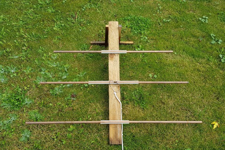
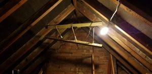
- A suitable Antenna pointed at your target beacon. Here’s mine – its made from copper pipe and a bit of wood. The antenna is connected to some 50 ohm coax cable and mounted in my loft using an old mobile-phone holder. See below for how to make the antenna.
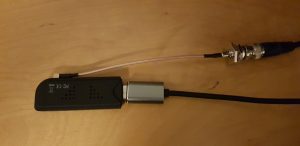
2) A Receiver. I’m using a Nooelec Nesdr SMart v4 RTL-SDR dongle i bought online. You will also need an adaptor to connect the BNC end of the coax to the antenna which is probably an SMA fitting (this older model uses a different connector).
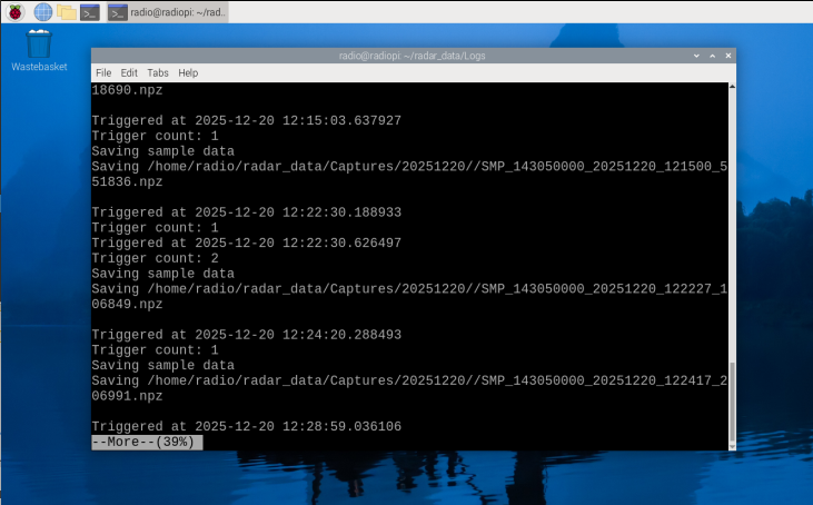
3) The software. I’m using Richard Bassom’s MeteorRadio software which runs on a Raspberry Pi and is available from Github here. The documentation in Github explains how to set everything up.
Building the Antenna
I wrote about this for the Society for Popular Astronomy in 2020. The text below is taken from that article:
We are going to make what’s called a “Three Element Yagi” antenna. This consists of three parallel metal elements called the Director, Reflector and Active element on an insulating support with the Active element connected to the aerial cable. The Antenna has to be “tuned” to the frequency you’re going to listen to – more on that later.
You will need a 3 metre length of 15mm copper pipe, a length of 50x50mm timber at least 650mm long, a 1m length of 15mm electrical square-section mini-trunking (the type with a top that pulls off), a length of coaxial cable to go from your antenna to your PC and a ‘pigtail’ connector to attach the coax to the USB dongle’s antenna socket. Check the dongle to see what connector it requires before buying the pigtail. You’ll also need a couple of small self-tapping screws with washers, and some wood screws to attach the trunking to the wood. Note that the Coax should be RG-58 as it has the right electrical characteristics. Ordinary TV Aerial cable will work but be less sensitive.
Earlier on I mentioned “tuning” the antenna to match the transmitter. We do this by cutting the elements to specific lengths and placing them just the right distance apart. The instructions below are therefore designed for one specific frequency – that of the GRAVES transmitter at 143.050 MHz. For other frequencies the lengths and spacings are different. The UK Beacon is at 50MHz – you can work out the required dimensions using the calculator here (other calculators are available!)
So here’s how to make your Antenna:
- Cut the copper pipe into four: 1076mm, 836mm, and two of 479mm.
- Cut the mini-trunking into three: two 25cm and one 50cm. Discard the tops.
- Draw three lines across the wooden boom at right angles. The first should be 100mm from one end, the next 265mm from the first mark and the last 235mm from the second. Label them R, A and D respectively.
- Screw the short pieces of mini-trunking to the boom at R and D. Use a set-square to get them exactly at right angles to the boom.
- Screw the long piece of mini-trunking on at A, again exactly at right angles.
- Drill two small holes in the ends of the shortest lengths of pipe and screw in the self-tapping screws with two washers each. This is where you’ll attach the coaxial cable.
- Clip the longest length of pipe into at R and the medium length into at D, making sure they are central.
- Clip the two short lengths of pipe into each side of A, with the screws in the middle. Leave a 15mm gap between the ends.
- Strip about 30mm from one end of the coaxial cable. Attach the core to one screw and the braiding to the other, then cover the two screws and the end of the cable in silicone sealant to keep water out.
Your finished article should look like the image above.
Siting the Antenna
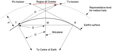
The antenna should be aimed at a point about 100 miles above the ground, half-way between you and your chosen transmitter. A bit of trigonometry will give you a decent estimate of this, but don’t forget that the Earth curves by about 10km in every 350 km. At the long wavelength that we’re using the radio waves will pass straight through roofs, trees and buildings but probably not a mountain.
I’m using GRAVES which is about 700 miles away to my South East (bearing 130) and I need to tilt my antenna up about 15 degrees. as shown here.
Thats pretty much it. The software will capture detections in a compressed data format. Uing the tools in Richard’s programme, you can review the images, create 2d and 3d spectrograms, create an audio sound of the event, and generate files for sharing with Radio Meteor enthusiasts.
Hi Mark, I find the possibility of using a RPi for automated radio detection of meteors appealing and have recently been following your described approach. I have encountered a significant issue in getting Bassom’s MeteorRadio software to run, however, and as someone who has clearly got this running I thought that you might be able to offer some helpful advice! In brief, I’ve followed the software installation instructions on GitHub and my RTL SDR dongle was detected ok after executing the rtl_test prog. When it finally came to running the actual python acquisition prog itself (meteor_radar.py) I realised that this was not present in the named directory (~/vMeteorRadio/bin) so downloaded this source code from GitHub. Attempting then to run this via the RPi terminal generates a Python ModuleNotFoundError on line 3 relating to the rtlsdr module. This initially seemed odd as it looks as though this should exist following the earlier installation of the required apt packages and my dongle test. I suspect, however, that I’m misunderstanding if the various Python sourcecode modules (e.g. for subsequent data analysis etc) need to be individually downloaded given that the meteor_radar.py prog was originally not present as described above? Any guidance that you can offer on where I might be misunderstanding how to successfully get this software running would be gratefully appreciated. With advanced thanks, DG